Clark's LA Courthouse Team Unveils 'Floating' Cube
June 29, 2015
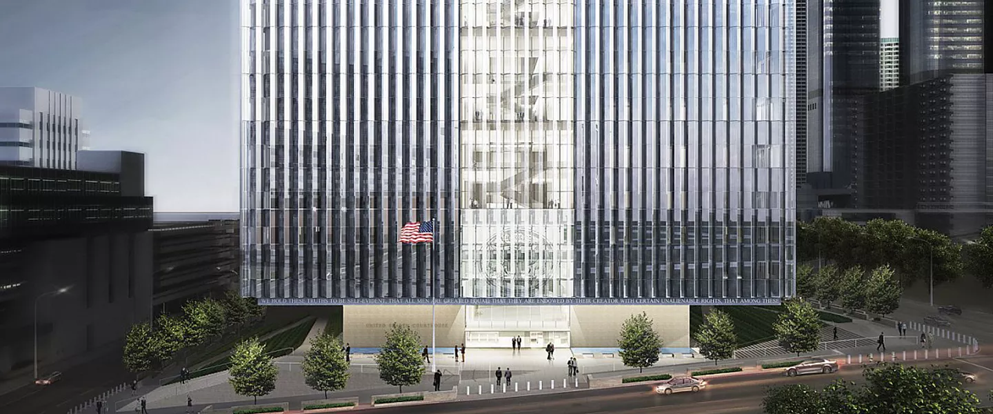
LOS ANGELES – Clark's Los Angeles U.S. Courthouse project team achieved a major milestone last month, completing the 'let-down' of the building. The design-build team, which includes architect Skidmore, Owings & Merrill (SOM), has been planning for this milestone since the 'floating cube' structure was conceived three years ago.
To achieve the desired floating cube effect, SOM devised a design in which the building's 35-foot cantilevered structure would hang from 24 columns supported by a unique truss system nine floors above. Each of the columns used to support the cantilever endured elements of compression during the erection phase, and, ultimately will endure tension for the rest of their structural life.
During the building's conceptual design phase, SOM proposed a truss scheme that incorporated parallel top and bottom chords. This design required typical floors to be elevated as much as 3 1/2 inches along the perimeter bays. To support SOM's initial design, the building would have to be jacked at the roof level to remove the temporary shoring columns. Clark had questions about constructability, specifically the varying floor elevations and whether or not the actual end product would match SOM's design intent. Based on our input, SOM produced several iterative models in order to develop the final truss scheme, which leveraged the concentric properties of a wagon wheel pattern. The final design approach allowed the building to be raised from the basement level in lieu of the roof. In order for the elastic properties to unfold with their final design, SOM calculated the projected elasticity for each column on every floor, which ranged from 1/2 inch at the roof level to 1 3/8 inch at the building's second floor. On paper, these calculations seemed trivial, but in reality, achieving these results was critical.
To bring the cube design to life, Clark enlisted the expertise of Herrick Steel to fabricate and erect the structure. Before construction began, Herrick drew up plans to temporarily shore the building's second floor, where the building cantilevered out 35 feet. Borrowing from SOM's design, Herrick installed 24, 42-inch-diameter steel columns, each 50+ feet in height, to support the perimeter structure during the nine-month erection phase. It took an additional two months to field weld the truss connections used to support the hanging structural system. After nearly a year, SOM's vision was ready to come to life as Herrick released the temporary shoring, revealing the 'floating cube' structure.
Jacking up the building to remove temporary shoring took months of planning. Herrick employed a series of hydraulic jacks to raise the building just enough to remove temporary shims 3/4 of an inch at a time. Herrick steelworkers completed the task in just two days and the building was free. The building's second floor columns elongated an average of 1 5/8 inch compared to their projection of 1 3/8 inch, resulting within 1/4 inch to the overall calculated elasticity.
After the building was free and performing within its designed tolerances, it took another week to remove all 24 temporary shoring columns. Once removed, the 'floating cube' design was complete.